| | |
| | Read through all of the instructions before starting installation. Notifications and warning texts are for your safety and to minimise the risk of something breaking during installation. Ensure that all tools stated in the instructions are available before starting installation. Certain steps in the instructions are only presented in the form of images. Explanatory text is also given for more complicated steps. In the event of any problems with the instructions or the accessory, contact your local Volvo dealer.
|
| | |
| | There may be parts in the accessories kit that are not needed for this installation. |
| | |
|  | | IMG-363036 |
|
| | Note!
This colour chart displays (in colour print and electronic version) the importance of the different colours used in the images of the method steps. |
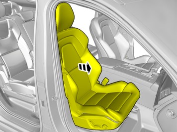
Used for focused component, the component with which you will do something. Used as extra colors when you need to show or differentiate additional parts. Used for attachments that are to be removed/installed. May be screws, clips, connectors, etc. Used when the component is not fully removed from the vehicle but only hung to the side. Used for standard tools and special tools. Used as background color for vehicle components.
|
| | |
| | Note!
The removal steps may contain installation details. |
|
|  | | IMG-394500 |
|
| | |
|  | | IMG-394038 |
|
| | |
|  | | IMG-394018 |
|
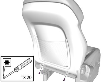
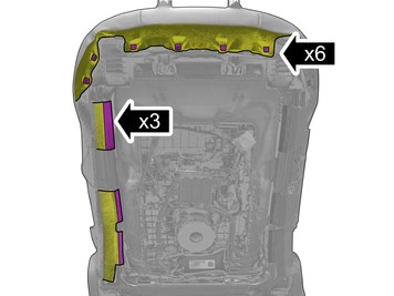
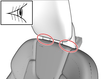
| | Note!
The graphic shows the back of the component before removal. |
|
|  | | IMG-394039 |
|
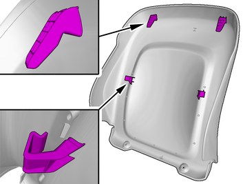
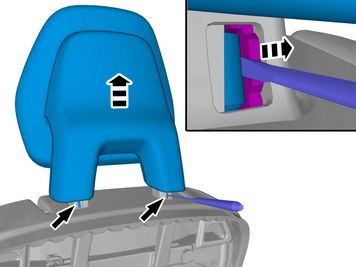
| | Note!
Perform the procedure one side at a time. |
|
|  | | IMG-394056 |
|
| | |
|  | | IMG-399420 |
|
| | |
|  | | IMG-403590 |
|
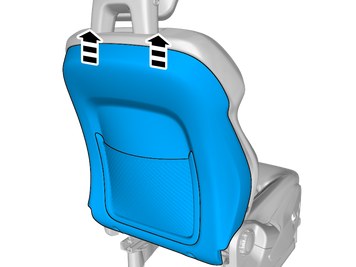
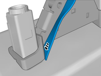
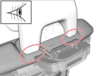
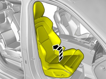
| | The image shows seat without upholstery. Release the locks. Remove the marked part. |
|  | | IMG-403751 |
|
| | Note!
The graphic shows the back of the component before removal. |
|
|  | | IMG-403745 |
|
| | |
| | |
| | Concerns installation of accessories on both seats |
|  | | IMG-405590 |
|
| | Install component that comes with the accessory kit. Ensure that all clips engage. |
|  | | IMG-421018 |
|
| | |
|  | | IMG-421016 |
|
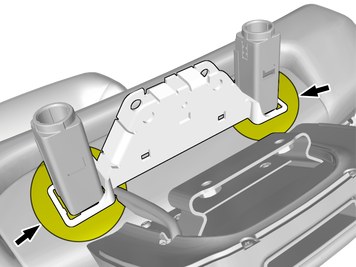
| | Install component that comes with the accessory kit. Make sure that the gasket is correctly located. |
|  | | IMG-420767 |
|
| | |
|  | | IMG-405870 |
|
| | |
|  | | IMG-405800 |
|
| | |
|  | | IMG-420792 |
|
| | |
|  | | IMG-408170 |
|
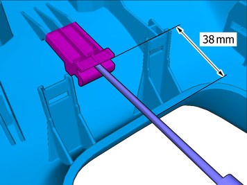
| | Note!
This step is easier with two people. |
Adjust to the specified value. |
|  | | IMG-420816 |
|
| | Note!
This step is easier with two people. |
Tighten the bolts. |
|  | | IMG-420842 |
|
| | Position/route the cable harness as illustrated. |
|  | | IMG-406221 |
|
| | |
|  | | IMG-407340 |
|
| | Caution!
Pull up the upholstery to cover lower part of bracket. |
|
|  | | IMG-407341 |
|
| | Caution!
Press the foam padding upward against the upholstery. |
|
|  | | IMG-405592 |
|
| | Caution!
Check that the component has locked in its bottom position. |
|
|  | | IMG-414067 |
|
| | Note!
Make sure that the backrest upholstery touches the head restraint, showing no space in between. |
Compare with upholstery and head restraint on the other front seat. |
|  | | IMG-413617 |
|
| | Note!
Make sure that the backrest upholstery touches the head restraint, showing no space in between. |
Compare with upholstery and head restraint on the other front seat. If adjustment is necessary, follow the procedure described in the method step below. |
| | | IMG-407341 |
|
| | Caution!
Press the foam padding upward against the upholstery. |
|
|  | | IMG-420877 |
|
| | Place the component where indicated in the graphic. Adjust the position of the wiring harness. |
|  | | IMG-421060 |
|
| | Install the screws. Make sure that the gasket is correctly located. Tighten the bolts. |
|  | | IMG-421061 |
|
| | Install component that comes with the accessory kit. |
|  | | IMG-421022 |
|
| | Install component that comes with the accessory kit. Position/route the cable as illustrated. Tighten the cable ties. |
|  | | IMG-423633 |
|
| | Position/route the cable as illustrated. |
|  | | IMG-420895 |
|
| | |
| | |
|  | | IMG-383130 |
|
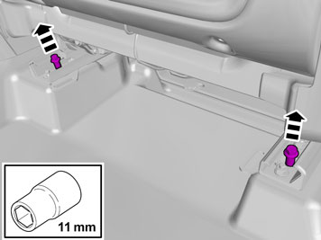
| | Remove the screws.
Tightening torque: Front seat to body
, 40 Nm
|
|  | | IMG-397249 |
|
| | |
|  | | IMG-383129 |
|
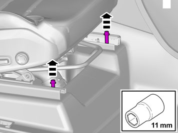
| | Remove the screws.
Tightening torque: Front seat to body
, 40 Nm
|
|  | | IMG-397252 |
|
| | |
|  | | IMG-396605 |
|
| | Release the connector's catch. Release the lock. Disconnect the connector.
|
|  | | IMG-396606 |
|
| | Unhook the cable harness clips. |
|  | | IMG-383729 |
|
| | |
|  | | IMG-433856 |
|
| | Remove the screw. Fold marked part aside. |
| | |
|  | | IMG-420976 |
|
| | View from below Position/route the cable as illustrated. Tighten the cable ties. |
|  | | IMG-421360 |
|
| | Install components that come with the accessory kit. Remove the protective film. |
|  | | IMG-423670 |
|
| | |
|  | | IMG-433798 |
|
| | Install component that comes with the accessory kit. |
|  | | IMG-421135 |
|
| | Place any excess inside the floor carpet. |
|  | | IMG-421251 |
|
| | View from below Position/route the cable as illustrated. Tighten the cable tie. |
| | Vehicles with 2-zone Air Conditioning system A/C |
|  | | IMG-394435 |
|
| | Disconnect the connector. |
|  | | IMG-433971 |
|
| | |
| | Vehicles with 4-zone Air Conditioning system A/C |
|  | | IMG-433990 |
|
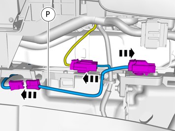
| | Depress the locking device. Disconnect the connector. Fold marked part aside. |
|  | | IMG-434149 |
|
| | Install component that comes with the accessory kit. Connect the connectors. |
| | |
|  | | IMG-406061 |
|
| | |
|  | | IMG-406062 |
|
| | Install the wiring harness. |
| | Concerns installation of accessories on both seats |
| | Repeat the steps when installing accessories on opposite side. |
| | |
| | Reinstall the removed parts in reverse order. |
| | Change of region code media player 7", according to service information in Vida. |
| | Information / Repair / Cleaning, Inspection and Adjustment / 3 Electrical systems / 39 Media, communication and navigation / 393 Equipment for entertainment (radio/TV/VCR) / Media player 7", change of region code |


