| | |
| | Read through all of the instructions before starting installation. Notifications and warning texts are for your safety and to minimise the risk of something breaking during installation. Ensure that all tools stated in the instructions are available before starting installation. Certain steps in the instructions are only presented in the form of images. Explanatory text is also given for more complicated steps. In the event of any problems with the instructions or the accessory, contact your local Volvo dealer.
|
| | |
|  | | IMG-363036 |
|
| | Note!
This colour chart displays (in colour print and electronic version) the importance of the different colours used in the images of the method steps. |
Used for focused component, the component with which you will do something. Used as extra colors when you need to show or differentiate additional parts. Used for attachments that are to be removed/installed. May be screws, clips, connectors, etc. Used when the component is not fully removed from the vehicle but only hung to the side. Used for standard tools and special tools. Used as background color for vehicle components.
|
| | |
|  | | IMG-416095 |
|
| | Release the connector's catch. Disconnect the connector. |
|  | | IMG-416097 |
|
| | |
|  | | IMG-416098 |
|
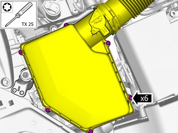
| | Lift the marked component up |
|  | | IMG-416099 |
|
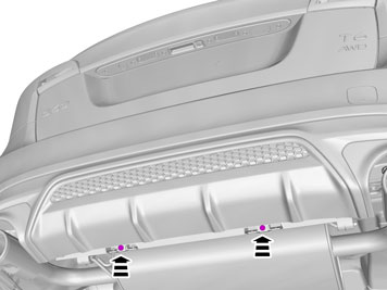
| | Lift the marked component up Remove the marked part. The part is not to be reused. |
| | |
|  | | IMG-416301 |
|
| | Install component that comes with the accessory kit. |
|  | | IMG-416101 |
|
| | Reinstall the removed part. |
|  | | IMG-416102 |
|
| | |
|  | | IMG-416105 |
|
| | |
|  | | IMG-418585 |
|
| | Clean the surface. Use: , Isopropanol
|
|  | | IMG-418586 |
|
| | Install component that comes with the accessory kit. |
| | |
|  | | IMG-350971 |
|
| | |
|  | | IMG-350912 |
|
| | |
|  | | IMG-421627 |
|
| | |
|  | | IMG-421628 |
|
| | |
|  | | IMG-421629 |
|
| | |
|  | | IMG-421630 |
|
| | |
|  | | IMG-421617 |
|
| | Remove the marked part. The part is not to be reused. |
|  | | IMG-421623 |
|
| | |
|  | | IMG-421624 |
|
| | |
|  | | IMG-381538 |
|
| | |
| | |
|  | | IMG-343213 |
|
| | |
| | |
|  | | IMG-337277 |
|
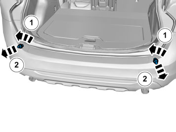
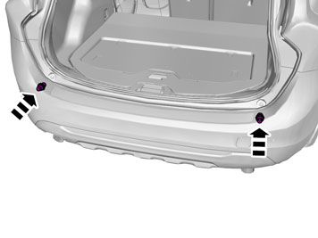
| | Remove the screws. On both sides. |
|  | | IMG-337279 |
|
| | Request the aid of a colleague for this procedure. |
| | Vehicles with parking assistance |
|  | | IMG-347701 |
|
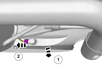
| | Disconnect the connectors. On both sides. |
|  | | IMG-347702 |
|
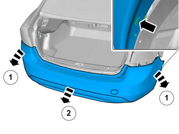
| | Remove the marked part. On both sides. |
|  | | IMG-337311 |
|
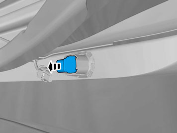
| | Disconnect the connector. |
|  | | IMG-347703 |
|
| | |
| | |
|  | | IMG-418700 |
|
| | Remove the screws. On both sides. |
|  | | IMG-418701 |
|
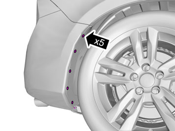
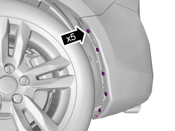
| | Remove the clips. On both sides. |
|  | | IMG-418706 |
|
| | |
|  | | IMG-418702 |
|
| | |
| | |
|  | | IMG-419136 |
|
| | Install component that comes with the accessory kit. |
| | |
|  | | IMG-418752 |
|
| | Cut the component following the instructions in the graphic. |
| | Vehicles with parking assistance |
|  | | IMG-377956 |
|
| | Reinstall the removed part. |
|  | | IMG-419169 |
|
| | Remove the clip. The part is not to be reused. |
|  | | IMG-421693 |
|
| | Install component that comes with the accessory kit. |
|  | | IMG-421695 |
|
| | Install component that comes with the accessory kit. Install the clips as illustrated. |
|  | | IMG-421697 |
|
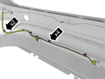
| | Install component that comes with the accessory kit. Connect the connectors. Position/route the cable harness as illustrated. |
|  | | IMG-337324 |
|
| | Place the Bumper Cover in position for installation. Connect the connector. |
| | |
| 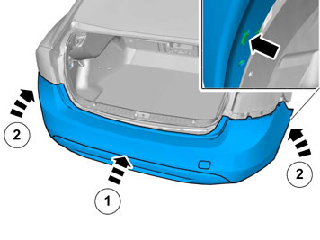 | | IMG-338572 |
|
| | Note!
This step is easier with two people. |
|
| | |
|  | | IMG-347831 |
|
| | Reinstall the removed part. |
| | |
|  | | IMG-337278 |
|
| | Install the screws. On both sides. |
| | | IMG-381538 |
|
| | |
|  | | IMG-421616 |
|
| | Install component that comes with the accessory kit. |
|  | | IMG-421618 |
|
| | Install component that comes with the accessory kit. |
|  | | IMG-421619 |
|
| | Note!
Do not fully tighten the nuts yet. |
Install component that comes with the accessory kit. |
|  | | IMG-421632 |
|
| | Press the marked component. |
|  | | IMG-421615 |
|
| | Tighten the nuts.
Tightening torque: M8
, 24 Nm
|
|  | | IMG-421620 |
|
| | Install component that comes with the accessory kit. |
|  | | IMG-421631 |
|
| | Press the marked component. |
|  | | IMG-416182 |
|
| | Tighten the nut.
Tightening torque: Exhaust clamp
, 60 Nm
|
|  | | IMG-421621 |
|
| | Install component that comes with the accessory kit. |
|  | | IMG-421622 |
|
| | |
|  | | IMG-421625 |
|
| | Note!
Do not fully tighten the bolts. |
Install component that comes with the accessory kit. |
|  | | IMG-421633 |
|
| | Note!
Do not fully tighten the bolts. |
Install component that comes with the accessory kit. |
|  | | IMG-416819 |
|
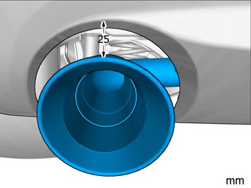
| | Adjust to the specified value. On both sides. |
|  | | IMG-416187 |
|
| | Note!
Make sure that the component is centred. |
|
|  | | IMG-421626 |
|
| |
Tightening torque: M8
, 24 Nm
|
|  | | IMG-418787 |
|
| | Adjust to the specified value. On both sides. |
|  | | IMG-419310 |
|
| | Note!
Make sure that the component is centred. |
|
|  | | IMG-416824 |
|
| |
Tightening torque: End pipe, to Muffler (Allen screw)
, 5 Nm
On both sides. |