| | |
|  | | IMG-346082 |
|
| | |
|  | | IMG-352601 |
|
| | |
| | | IMG-346082 |
|
| | |
|  | | IMG-352603 |
|
| | |
|  | | IMG-352606 |
|
| | Note!
Also read the instructions on the spray can. |
|
|  | | IMG-346087 |
|
| | Note!
Also read the instructions on the spray can. |
|
|  | | IMG-346086 |
|
| | Caution!
Protect the connections' contact surfaces against paint. |
Paint the sensors in the same colour code as the vehicle. Use Volvo Touch-up paint (Only use base coat.) Use: Volvo 2-K Varnish. P/N: 31335447
Note!
Also read the instructions on the spray can. |
|
| | | IMG-346087 |
|
| | Paint the holders in the same colour code as the vehicle. Use Volvo Touch-up paint (Only use base coat.) Use: Volvo 2-K Varnish. P/N: 31335447
Note!
Also read the instructions on the spray can. |
|
|  | | IMG-332193 |
|
| | Note!
Wait at least one minute before unplugging the connectors or removing other electrical equipment. |
|
|  | | IMG-273472 |
|
| | |
|  | | IMG-273474 |
|
| | Prize off the four external clips at the front edge/bottom edge of the sill trim panel on the tailgate. Pry up one of the corners of the sill trim panel so that the two clips at that end release. Use a weatherstrip tool. Pull up the sill trim panel so the remaining six clips release. Remove the panel.
|
|  | | J8504578 |
|
| | |
|  | | J8504708 |
|
| | |
|  | | IMG-240927 |
|
| | |
|  | | IMG-347037 |
|
| | Fold out the anchorage eyelets. Insert a scriber with an angled tip into the holes in the top of the covers (1). Turn the scriber so that the tip engages the reverse of the cover. Pull the covers off. Remove the screws from the anchorage eyelets (2). Remove the screw (3). Pull off the side panel at the top so that the two clips at the rear/bottom of the side window and the clip at the bottom of the D-pillar release. Disconnect the connector for the 12V socket, if present. Lift out the side panel.
|
|  | | IMG-273475 |
|
| | |
|  | | J8601058 |
|
| | |
|  | | J8504526 |
|
| | |
|  | | J8504527 |
|
| | Note!
It is recommended that two people lift down the bumper cover. |
|
|  | | IMG-346088 |
|
| | |
|  | | IMG-346089 |
|
| | |
|  | | IMG-346090 |
|
| | |
|  | | IMG-346091 |
|
| | Caution!
Place the hole tool's support sleeve on the inside, and the cutting part on the outside of the bumper casing. |
Make the holes in the bumper cover using the hole tool. Screw the hole tool together until it has cut the hole in the bumper cover. Remove the plastic pieces from the hole tool and make the remaining holes in the same way.
|
|  | | IMG-346092 |
|
| | |
|  | | IMG-346093 |
|
| | |
|  | | IMG-346094 |
|
| | |
|  | | IMG-346095 |
|
| | |
|  | | J8601193 |
|
| | |
|  | | J8601273 |
|
| | Applies to cars with the Keyless system |
|  | | IMG-347023 |
|
| | Applies to cars with a tow hitch |
|  | | IMG-222068 |
|
| | |
|  | | IMG-254283 |
|
| | Caution!
Note the location of the cables in the connector. |
Disconnect all cable lugs from the connector. Use special tool 9512810 or 9512632. Insert the tool in the connector and release the locking. Pull out the cable with cable lug. Pull the cable harness out through the rubber grommet. The rubber grommet is not to be reused.
|
|  | | J3703374 |
|
| | Hint
Lubricate the cable harness with something that will not damage the rubber grommet and route the cable harness through the hole. |
|
|  | | J8601274 |
|
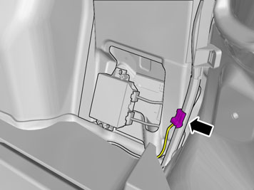
| | Applies to all models Take the cable harness with the rubber grommet from the kit. Pull in the end with four connectors through the hole in the car and fit the rubber grommet. Hook the connector (1) at the intended location under the tail lamp.
|
|  | | IMG-273518 |
|
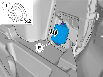
| | Applies to cars with the Keyless system Plug the connector into the antenna (1).
|
|  | | IMG-346098 |
|
| | |
|  | | IMG-346588 |
|
| | |
|  | | IMG-346589 |
|
| | |
|  | | IMG-346590 |
|
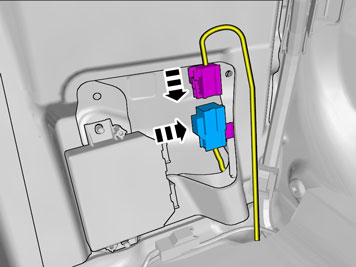
| | Applies to cars with the Keyless system Plug the gray connector into the corresponding gray connector.
|
|  | | IMG-346097 |
|
| | Applies to cars with TRM or TRM combined with AEM |
|  | | J3703662 |
|
| | Note!
It is important that the Parking Assistance Module (PAM) is connected as the first module and that the cable harnesses are connected correctly, and not in a loop. |
|
|  | | IMG-346591 |
|
| | Applies to cars with an accessory electronic module (AEM) |
| | | J3703662 |
|
| | Note!
It is important that the Parking Assistance Module (PAM) is connected as the first module and that the cable harnesses are connected correctly, and not in a loop. |
|
|  | | IMG-346099 |
|
| | |
|  | | IMG-346100 |
|
| | |
|  | | IMG-346101 |
|
| | Note!
Prepare and install one cradle at a time. |
Note!
The tape adheres immediately. |
|
|  | | IMG-346102 |
|
| | Caution!
The adhesive must not come into contact with the tape or the cradle's protruding ring. The task of the tape is to secure the cradles to the bumper cover until the adhesive has cured after approximately 24 hours. |
|
|  | | IMG-273503 |
|
| | Caution!
Only press on the places where the tape is located. |
|
|  | | IMG-346214 |
|
| | Caution!
Observe caution when installing so that the cradle does not come loose from the tape. |
Note!
The large gray connector must protrude from the right-hand side of the bumper cover. |
|
|  | | IMG-273505 |
|
| | |
|  | | IMG-273473 |
|
| | |
|  | | IMG-273562 |
|
| | |
|  | | IMG-242268 |
|
| | Gather together any excess cables. Clamp the cables securely where they cannot rub or become damaged. Refit the panels and remaining parts removed in reverse order. Download the software for the accessory's function following the service information in VIDA. Check the function.
|