| | |
| | Read through all of the instructions before starting installation. Notifications and warning texts are for your safety and to minimise the risk of something breaking during installation. Ensure that all tools stated in the instructions are available before starting installation. Certain steps in the instructions are only presented in the form of images. Explanatory text is also given for more complicated steps. In the event of any problems with the instructions or the accessory, contact your local Volvo dealer.
|
| | |
|  | | IMG-363036 |
|
| | Note!
This colour chart displays (in colour print and electronic version) the importance of the different colours used in the images of the method steps. |
Used for focused component, the component with which you will do something. Used as extra colors when you need to show or differentiate additional parts. Used for attachments that are to be removed/installed. May be screws, clips, connectors, etc. Used when the component is not fully removed from the vehicle but only hung to the side. Used for standard tools and special tools. Used as background color for vehicle components.
|
| | |
|  | | IMG-297185 |
|
| | |
|  | | IMG-377294 |
|
| | |
|  | | IMG-297503 |
|
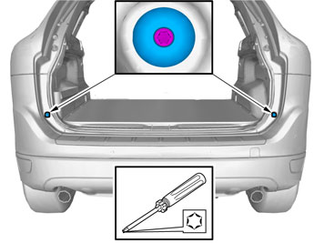
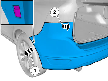
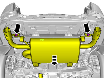
| | Remove the screws. Repeat on the other side. |
|  | | IMG-297504 |
|
| | Note!
This step is easier with two people. |
|
|  | | IMG-297523 |
|
| | Note!
This step is easier with two people. |
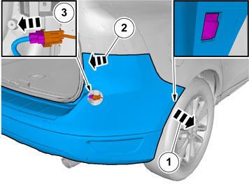
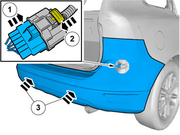
Disconnect the connector. |
|  | | IMG-285056 |
|
| | |
| | Vehicles with 2WD and 4-cyl gasoline engine |
|  | | IMG-259823 |
|
| | |
| | Vehicles with 2WD and 4-cyl diesel engine |
|  | | IMG-291744 |
|
| | |
| | Vehicles with 2WD and 5-cyl diesel engine |
| | | IMG-291744 |
|
| | |
| | Vehicles with AWD and 5-cyl diesel engine |
|  | | IMG-285059 |
|
| | |
| | Vehicles with AWD and 6-cyl gasoline engine |
|  | | IMG-259824 |
|
| | |
| | |
|  | | IMG-337287 |
|
| | |
|  | | IMG-285061 |
|
| | |
|  | | IMG-285063 |
|
| | |
|  | | IMG-285064 |
|
| | |
|  | | IMG-285065 |
|
| | Remove the tape. Repeat on the other side. |
|  | | IMG-285066 |
|
| | Clean the surface. Repeat on the other side. |
| | |
|  | | IMG-377536 |
|
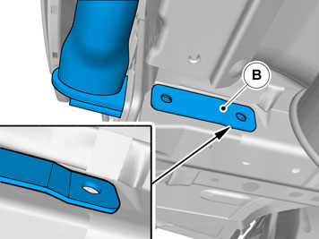
| | Install component that comes with the accessory kit. |
|  | | IMG-377153 |
|
| | Repeat on the other side. |
|  | | IMG-377154 |
|
| | Caution!
Make sure that the exhaust flexible pipe is not forcibly bent or twisted. |
Note!
This step is easier with two people. |
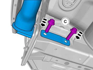
Note!
Only tighten the bolts finger tight at this stage. |
Install the screws. Repeat on the other side.
Use special tool: T9995972, FIXTURE (UNIVERSAL/TRANSAXLES)
Use special tool: T9985972, JACK (HYDRAULIC)
|
|  | | IMG-377167 |
|
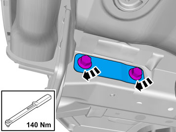
| | Repeat on the other side. |
|  | | IMG-377165 |
|
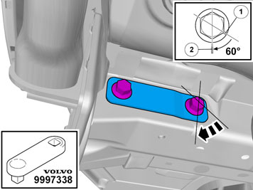
| | Repeat on the other side.
Use special tool: T9997338, Extension rod
|
| | |
|  | | IMG-285210 |
|
| | |
|  | | IMG-285086 |
|
| | |
|  | | IMG-290643 |
|
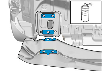
| | Caution!
Make sure to protect adjacent surfaces or components. |
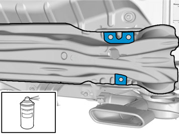
Use: 1161815, Stone-chip protection
|
|  | | IMG-344784 |
|
| | |
|  | | IMG-285212 |
|
| | |
| | Vehicles with 2WD and 4-cyl gasoline engine |
|  | | IMG-259874 |
|
| | |
| | Vehicles with 2WD and 4-cyl diesel engine |
|  | | IMG-292263 |
|
| | |
| | Vehicles with 2WD and 5-cyl diesel engine |
| | | IMG-292263 |
|
| | |
| | Vehicles with AWD and 5-cyl diesel engine |
|  | | IMG-285090 |
|
| | |
| | Vehicles with AWD and 6-cyl gasoline engine |
|  | | IMG-259873 |
|
| | |
| | |
|  | | IMG-377070 |
|
| | Install tow bar connector and wiring harness according to installation instruction: Towbar, Wiring and Control Unit. |
|  | | IMG-367201 |
|
| | Use: , Rust inhibitor, low viscosity
Repeat on the other side. |
|  | | IMG-367202 |
|
| | |
|  | | IMG-367329 |
|
| | Use: , Rust inhibitor, low viscosity
Repeat on the other side. |
|  | | IMG-285511 |
|
| | |
| | |
| | Vehicles with skidplate (accessory) |
|  | | IMG-377259 |
|
| | |
|  | | IMG-377643 |
|
| | |
|  | | IMG-377220 |
|
| | Apply tape to the other side, opposite the marking lines. |
|  | | IMG-377705 |
|
| | Remove the marked part. Use: Air-powered keyhole saw
|
|  | | IMG-377657 |
|
| | |
|  | | IMG-377692 |
|
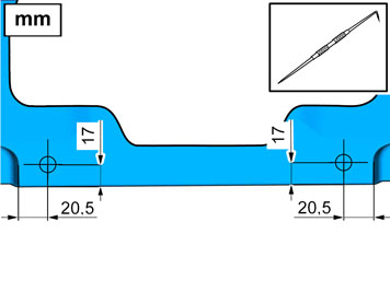
| | Measure and mark as illustrated. |
|  | | IMG-377698 |
|
| | |
|  | | IMG-377700 |
|
| | |
|  | | IMG-378350 |
|
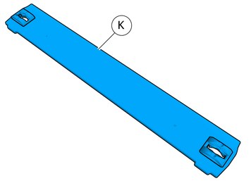
| | Install component that comes with the accessory kit. |
|  | | IMG-405782 |
|
| | |
|  | | IMG-405781 |
|
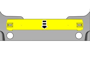
| | Place the component where indicated in the graphic. |
|  | | IMG-405795 |
|
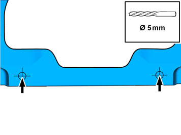
| | Locate the markings for the positions. Drill one hole and fit one pop rivet at a time, in accordance with the sequence illustrated. |
|  | | IMG-405797 |
|
| | Install component that comes with the accessory kit. |
|  | | IMG-377655 |
|
| | Install component that comes with the accessory kit. |
|  | | IMG-378655 |
|
| | |
|  | | IMG-378656 |
|
| | |
| | Vehicles with skidplate (standard) |
|  | | IMG-377258 |
|
| | |
|  | | IMG-407301 |
|
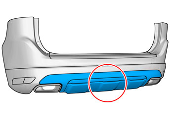
| | Locate relevant marking. Scribe/mark up |
| | | IMG-377220 |
|
| | Apply tape to the other side, opposite the marking lines. |
|  | | IMG-407303 |
|
| | Remove the marked part. Use: Air-powered keyhole saw
|
|  | | IMG-407311 |
|
| | |
| | | IMG-377698 |
|
| | |
| | | IMG-377700 |
|
| | |
| | | IMG-378350 |
|
| | Install component that comes with the accessory kit. |
| | | IMG-405782 |
|
| | |
| | | IMG-405781 |
|
| | Place the component where indicated in the graphic. |
| | | IMG-405795 |
|
| | Locate the markings for the positions. Drill one hole and fit one pop rivet at a time, in accordance with the sequence illustrated. |
| | | IMG-405797 |
|
| | Install component that comes with the accessory kit. |
| | | IMG-377655 |
|
| | Install component that comes with the accessory kit. |
| | | IMG-378655 |
|
| | |
| | | IMG-378656 |
|
| | |
| | |
|  | | IMG-377381 |
|
| | |
|  | | IMG-377732 |
|
| | |
|  | | IMG-377740 |
|
| | Apply tape to the other side, opposite the marking lines. |
|  | | IMG-377750 |
|
| | |
|  | | IMG-377752 |
|
| | |
| | |
|  | | IMG-297604 |
|
| | |
| | | IMG-297503 |
|
| | Install the screws. Repeat on the other side. |
| | | IMG-297185 |
|
| | |
|  | | IMG-285528 |
|
| | |
|  | | IMG-285529 |
|
| | |
|  | | IMG-292304 |
|
| | Take the label from the kit and attach it to the underneath of the cargo compartment mat as illustrated. |
|  | | IMG-285531 |
|
| | Take the label from the kit and attach it to the underneath of the cargo compartment mat as illustrated. Attach the four corners of the label using staples. |
|  | | IMG-290583 |
|
| | |
|  | | IMG-377188 |
|
| | |
|  | | IMG-285533 |
|
| | |
|  | | IMG-377565 |
|
| | |
|  | | IMG-285726 |
|
| | |
|  | | IMG-285534 |
|
| | |
| | |
|  | | IMG-372330 |
|
| | |
|  | | IMG-372215 |
|
| | |
|  | | IMG-372217 |
|
| | |