2014 D4 AUTOMATIC L.H.D

Инструкция по установке

Installation instructions, accessories
Volvo Car Corporation Gothenburg, Sweden
XC70 2014
XC70 (08-) 2014 L.H.D

Instruction NoVersionPart. No.Click to download PDF-version of this Installation Instruction
312608161.131260792
Tracker system based on Volvo on Call


Equipment
IMG-242205
A0000162
IMG-239664
IMG-334911

IMG-315383


INTRODUCTION

  • Read through all of the instructions before starting installation.

  • Notifications and warning texts are for your safety and to minimise the risk of something breaking during installation.

  • Ensure that all tools stated in the instructions are available before starting installation.

  • Certain steps in the instructions are only presented in the form of images. Explanatory text is also given for more complicated steps.

  • In the event of any problems with the instructions or the accessory, contact your local Volvo dealer.


Note!

The installation instructions only apply to left-hand drive cars


1
IMG-246024
 

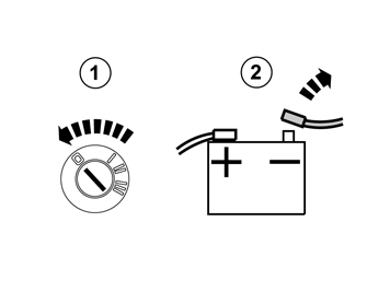
  • Turn the ignition switch to position 0.

  • Disconnect the battery negative lead.


Note!

Wait at least three minutes before unplugging the connectors or removing other electrical equipment.


2
IMG-239420
 

3
IMG-222268
 

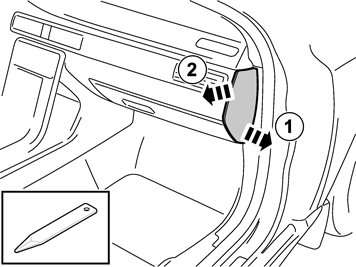
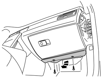
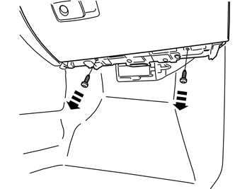
  • Remove the bolts of the panel underneath the glovebox and remove it.

4
IMG-222270
 

  • Disconnect the lighting connector and place the panel to one side.

5
IMG-225205
 

  • Remove the two screws.

6A
IMG-225201
6B
IMG-279924
6C
IMG-279925
 

A, B, and C

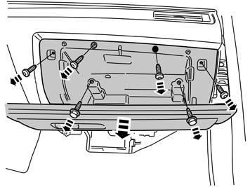
  • Remove the six screws.

  • Pull out the glove box slightly.

  • Disconnect the connector at the rear edge.

  • Remove the connectors on top and disconnect them.

  • Remove the glovebox.

7
IMG-315405
 

  • Remove the three screws in the control module and withdraw it from the holder. The screws will be reused.

8
IMG-315406
 

  • Disconnect the connectors from the control module and remove it.

9
IMG-315408
 

  • Remove the spring nuts. They will not be used again.

10
IMG-315409
 

11
IMG-315643
 

12
IMG-315644
 

13
IMG-315645
 

  • Take GPS-antenna from the kit and carefully file off the lug on the underside.

14A
IMG-315646
14B
IMG-315407
 

Illustrations A and B

  • Remove the GPS cable from the kit and insert it down through the hole in the dashboard at the right hand A-post.

  • Pull it out as illustrated in image B.

15
IMG-315647
 

16
IMG-315648
 

  • Place the GPS antenna on the insulation mat at the A-post as illustrated.

  • Pierce holes in the insulation mat on both sides of the antenna.

  • Move the GPS antenna.

17
IMG-315649
 

  • Thread a tie strap through the holes.

18
IMG-315651
 

  • Tighten the antenna against the insulation mat.

19
IMG-315650
 

  • Take a piece of butyl tape and lay it along the insulation mat and secure it against the A post so that the insulation mat tab is held in place.

20
IMG-315652
 

  • Clamp the GPS cable to the existing cable harness.

21
IMG-315653
 

22
IMG-315663
 

23
IMG-315664
 

24
IMG-315665
 

  • Install the control module in the bracket.

25
IMG-315666
 

  • Install the cover on the bracket.

26
IMG-315683
 

  • Position the control module where the glove box was located.

  • Connect the cable (1) from the GPS.

  • Connect other cables that were disconnected from the control module.

27A
IMG-315684
27B
IMG-334822
 

Illustrations A and B

  • Install the control module with brackets and tighten the three existing screws and security screw. Use insertion sleeve part.no. 9814114 when torque tightening. Ensure that the cables run correctly and do not risk being clamped or frayed.

28
IMG-225269
 

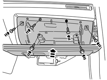
  • Take the glove box and connect the connectors on the reverse.

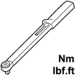
  • Reinstall the glove box and tighten the M6 bolts to 10 Nm (7.5 lbf.ft).

29
IMG-280026
 

  • Install the screws in the lower edge.

30
IMG-286608
 

31
IMG-225272
 

32
IMG-280033
 

33
IMG-242267
 

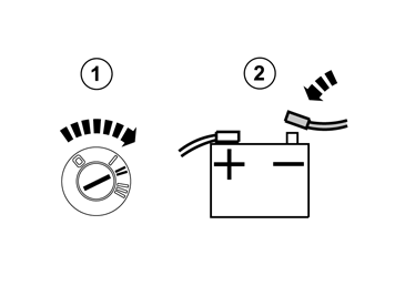
  • Turn the ignition key to position II.

  • Reconnect the battery negative lead

34
IMG-242268
 

  • Download the software for the accessory's function following the service information in VIDA.