| | |
| | Read through all of the instructions before starting installation. Notifications and warning texts are for your safety and to minimise the risk of something breaking during installation. Ensure that all tools stated in the instructions are available before starting installation. Certain steps in the instructions are only presented in the form of images. Explanatory text is also given for more complicated steps. In the event of any problems with the instructions or the accessory, contact your local Volvo dealer.
|
| | |
|  | | IMG-329148 |
|
| | |
|  | | IMG-329150 |
|
| | |
|  | | IMG-340980 |
|
| |
Tightening torque: Front seat to body
, 40 Nm
|
|  | | IMG-303005 |
|
| | |
|  | | IMG-303006 |
|
| |
Tightening torque: Front seat to body
, 40 Nm
|
| | |
|  | | IMG-329152 |
|
| | |
| | |
|  | | IMG-330333 |
|
| | |
|  | | IMG-330334 |
|
| | |
| | |
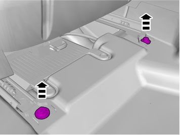
| | Repeat the steps when removing on opposite side. |
|  | | IMG-332179 |
|
| | |
|  | | IMG-292804 |
|
| | |
|  | | IMG-292806 |
|
| | Fold the carpet to the side. |
|  | | IMG-292823 |
|
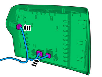
| | Remove the cable harness clips. Disconnect the connector.
|
|  | | IMG-292826 |
|
| | |
| | Vehicles with the 4C system. |
|  | | IMG-292827 |
|
| | Disconnect the connector. |
| | |
|  | | IMG-345728 |
|
| | |
|  | | IMG-345734 |
|
| | Disconnect the connector. |
|  | | IMG-292863 |
|
| | |
|  | | IMG-292883 |
|
| | Use: Electrician's screwdriver
|
|  | | IMG-293126 |
|
| | |
|  | | IMG-292884 |
|
| | |
|  | | IMG-345282 |
|
| | |
| | Cars with automatic transmissions |
|  | | IMG-345283 |
|
| | |
|  | | IMG-293007 |
|
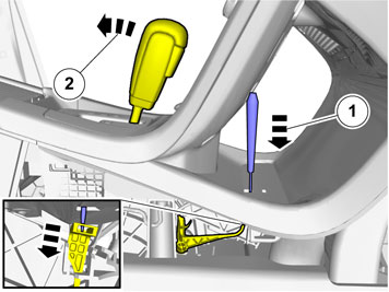
| | Release the shift-lock function. |
| | Cars with manual transmissions |
|  | | IMG-354293 |
|
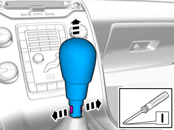
| | Release the catch which is located inside the gear lever boot. Pull the locking sleeve and gear lever boot down. Take care so that the boot does not come loose from the lock ring. |
|  | | IMG-347222 |
|
| | |
| | |
|  | | IMG-293009 |
|
| | |
|  | | IMG-293010 |
|
| | |
|  | | IMG-293011 |
|
| | |
|  | | IMG-293012 |
|
| | |
|  | | IMG-357464 |
|
| | Note!
The number of connectors may vary depending on the vehicle's equipment level. |
Disconnect the connectors. |
|  | | IMG-345774 |
|
| | |
|  | | IMG-345773 |
|
| | |
|  | | IMG-366441 |
|
| | Disconnect the connector, if applicable. Attach the connector to the wiring harness. Use: , Wiring tape
|
|  | | IMG-357469 |
|
| | Note!
The number of connectors may vary depending on the vehicle's equipment level. |
Disconnect the connectors. |
|  | | IMG-329151 |
|
| | |
|  | | IMG-329209 |
|
| | Remove the screws. Disconnect the connector. |
|  | | IMG-329153 |
|
| | Caution!
Be extra careful when removing or installing this component. |
|
|  | | IMG-358761 |
|
| | Use: Electrician's screwdriver
|
|  | | IMG-358762 |
|
| | |
| | Repeat the steps when removing on opposite side. |
| | |
|  | | IMG-360651 |
|
| | |
|  | | IMG-358776 |
|
| |
Use special tool: T9512932, Tension spring
|
|  | | IMG-358777 |
|
| | |
|  | | IMG-358631 |
|
| | |
|  | | IMG-358868 |
|
| | |
|  | | IMG-358872 |
|
| | |
|  | | IMG-344892 |
|
| | Route the cable harness to the existing cable harness. |
|  | | IMG-358665 |
|
| | |
|  | | IMG-358772 |
|
| | |
|  | | IMG-358779 |
|
| | |
|  | | IMG-358676 |
|
| | |
|  | | IMG-357602 |
|
| | |
|  | | IMG-358780 |
|
| | |
|  | | IMG-357606 |
|
| | |
|  | | IMG-357611 |
|
| | |
|  | | IMG-357612 |
|
| | |
|  | | IMG-358689 |
|
| | |
| | Repeat the steps when installing accessories on opposite side. |
| | |
|  | | IMG-308353 |
|
| | |
|  | | IMG-344927 |
|
| | |
|  | | IMG-286863 |
|
| | Caution!
The front and upper sill panel must be removed and installed as one unit. |
|
|  | | IMG-308355 |
|
| | |
|  | | IMG-308356 |
|
| | |
|  | | IMG-344451 |
|
| | |
|  | | IMG-355782 |
|
| | Remove the screws. Detach the panel. |
|  | | IMG-355781 |
|
| | Disconnect the connector. |
|  | | IMG-357907 |
|
| | |
|  | | IMG-357908 |
|
| | |
|  | | IMG-357909 |
|
| | Unhook the cable harness clips. |
|  | | IMG-356889 |
|
| | Disconnect the connector. |
|  | | IMG-361286 |
|
| | |
|  | | IMG-359567 |
|
| | |
|  | | IMG-359565 |
|
| | |
|  | | IMG-359564 |
|
| | |
| | |
|  | | IMG-359563 |
|
| | |
|  | | IMG-359566 |
|
| | |
|  | | IMG-359562 |
|
| | |
|  | | IMG-359590 |
|
| | |
|  | | IMG-359592 |
|
| | Note!
Only tighten the bolt finger tight at this stage. |
|
|  | | IMG-359591 |
|
| | Note!
Only tighten the bolt finger tight at this stage. |
|
|  | | IMG-358786 |
|
| | |
|  | | IMG-357694 |
|
| | |
|  | | IMG-359625 |
|
| | |
|  | | IMG-359626 |
|
| | |
|  | | IMG-357736 |
|
| | Route the cable harness to the existing cable harness. |
|  | | IMG-357796 |
|
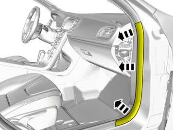
| | Fold the carpet to the side. |
|  | | IMG-269505 |
|
| | |
|  | | IMG-282896 |
|
| | |
|  | | IMG-357774 |
|
| | |
|  | | IMG-357775 |
|
| | Release the lock. Disconnect the connector. |
|  | | IMG-358550 |
|
| | Use: Electrician's screwdriver
|
|  | | IMG-358551 |
|
| | Release the connector's secondary lock. |
|  | | IMG-357776 |
|
| | Connect the cable harness. |
|  | | IMG-303794 |
|
| | |
|  | | IMG-359818 |
|
| | |
|  | | IMG-359817 |
|
| | |
|  | | IMG-357468 |
|
| | |
|  | | IMG-357463 |
|
| | Connect the cable harness. |
|  | | IMG-359569 |
|
| | |
|  | | IMG-359841 |
|
| | |
|  | | IMG-359842 |
|
| | |
|  | | IMG-357848 |
|
| | Connect the cable harness. |
|  | | IMG-357854 |
|
| | |
|  | | IMG-357856 |
|
| | Connect the cable harness. |
|  | | IMG-359568 |
|
| | |
|  | | IMG-357925 |
|
| | |
|  | | IMG-357933 |
|
| | |
| | |
|  | | IMG-360753 |
|
| | |
|  | | IMG-360754 |
|
| | |
|  | | IMG-360755 |
|
| | |
|  | | IMG-341777 |
|
| | |
| | Vehicles with headset sockets |
|  | | IMG-293025 |
|
| | |
|  | | IMG-293026 |
|
| | Disconnect the connector. The part is not to be reused. |
| | |
|  | | IMG-293021 |
|
| | |
|  | | IMG-329163 |
|
| | |
|  | | IMG-293028 |
|
| | |
|  | | IMG-293024 |
|
| | |
|  | | IMG-293029 |
|
| | |
| | Vehicles with headset sockets |
|  | | IMG-360286 |
|
| | The part is not to be reused. |
| | |
|  | | IMG-360278 |
|
| | Disconnect the connectors. |
|  | | IMG-329164 |
|
| | |
|  | | IMG-293022 |
|
| | |
|  | | IMG-293023 |
|
| | |
|  | | IMG-360287 |
|
| | |
|  | | IMG-360397 |
|
| | |
|  | | IMG-360556 |
|
| | |
|  | | IMG-360533 |
|
| | Unhook the cable harness clips. Remove the tape. Reuse existing parts. |
| | |
|  | | IMG-360532 |
|
| | Remove the cable harness clips. Disconnect the connector. |
| | |
|  | | IMG-360624 |
|
| | Remove the cable harness clips. Disconnect the connector. |
|  | | IMG-360531 |
|
| | |
|  | | IMG-360394 |
|
| | |
|  | | IMG-360393 |
|
| | |
|  | | IMG-360401 |
|
| | |
| | |
|  | | IMG-360391 |
|
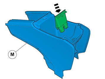
| | Install component that comes with the accessory kit. |
|  | | IMG-360418 |
|
| | |
| | |
|  | | IMG-360422 |
|
| | |
| | | IMG-360394 |
|
| | |
|  | | IMG-360423 |
|
| | |
|  | | IMG-360635 |
|
| | |
| | |
|  | | IMG-360637 |
|
| | |
| | |
|  | | IMG-360638 |
|
| | |
|  | | IMG-360640 |
|
| | |
|  | | IMG-360641 |
|
| | |
| | |
|  | | IMG-360642 |
|
| | |
|  | | IMG-360646 |
|
| | Connect the cable harness. |
|  | | IMG-357986 |
|
| | |
|  | | IMG-358064 |
|
| | |
|  | | IMG-358052 |
|
| | |
|  | | IMG-358067 |
|
| | |
|  | | IMG-303848 |
|
| | |
|  | | IMG-358001 |
|
| | |
|  | | IMG-358002 |
|
| |
Tightening torque: M6
, 10 Nm
|
|  | | IMG-358065 |
|
| | |
| | |
|  | | IMG-329473 |
|
| | |
|  | | IMG-358602 |
|
| | Connect the cable harness. |
|  | | IMG-329270 |
|
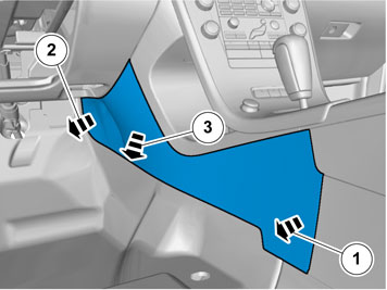
| | Connect the connector. Tighten the screw. |
| | Repeat the steps when installing on opposite side. |
| | Reinstall the removed parts in reverse order. |
|  | | IMG-336901 |
|
| | |
|  | | IMG-336904 |
|
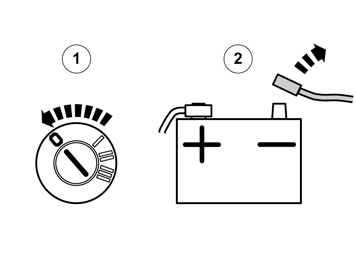
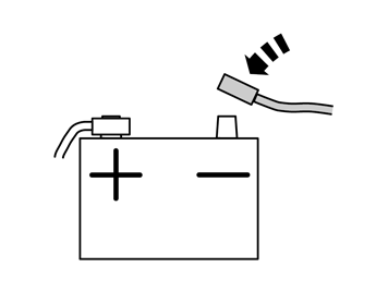
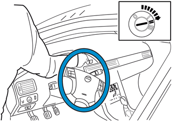
| | Warning!
When switching the ignition on for the first time after a battery disconnect and connect, make sure to stand outside the vehicle and only reach into the vehicle keeping clear of the air bag deployment areas. |
|
|  | | IMG-242268 |
|
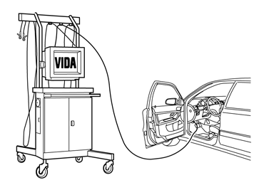
| | Download software (application) for the accessory's function according to the service information in VIDA. See VIDA or the accessories catalogue for software part number. |
|  | | IMG-358847 |
|
| | |
|  | | IMG-358846 |
|
| | |