2006 D5 AWD AUTOMATIC R.H.D

Installation Instruction

Installation instructions, accessories
Volvo Car Corporation Gothenburg, Sweden
XC90 2006
XC90 (03-) 2006

Instruction NoVersionPart. No.Click to download PDF-version of this Installation Instruction
307563061.531285225, 31285223
Navigation system, portable


IMG-280105


Equipment
A0000162
IMG-282403
IMG-246925
IMG-239660
IMG-239667
IMG-240673
IMG-239681

IMG-280472

IMG-280106

IMG-213320


INTRODUCTION

  • Read through all of the instructions before starting installation.

  • Notifications and warning texts are for your safety and to minimise the risk of something breaking during installation.

  • Ensure that all tools stated in the instructions are available before starting installation.

  • Certain steps in the instructions are only presented in the form of images. Explanatory text is also given for more complicated steps.

  • In the event of any problems with the instructions or the accessory, contact your local Volvo dealer.


Note!

For information regarding the GARMIN device, see www.garmin.com.


Note!

Some steps in these installation instructions are presented with illustration only.


Assembling the holder

1
IMG-296185
 

Assembling the holder


Note!

Take care when handling the components, they are fragile and are easily damaged.


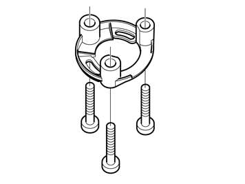
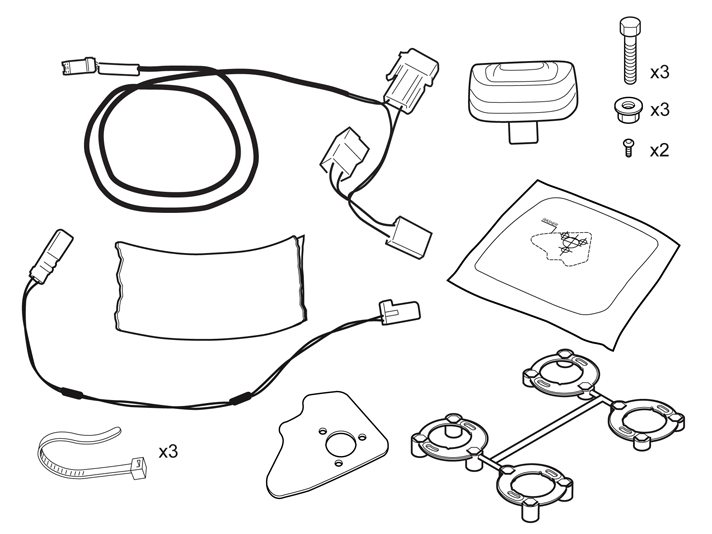
  • Take the three screws M5x20 part no. 986956 and nuts from the kit.

  • To prevent too great resistance when the nut for the holder is tightened, hold the screw and screw the nut on and off the threaded part of the screw. Carry this out on all screws and nuts.

2
IMG-282404
 

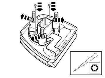
  • Take special tool 9814104 (torx driver, torx 6), and unscrew the two screws holding the connector in the holder.

  • Carefully push the connector to one side with the cable to expose the bottom of the holder.

3
IMG-282405
 

  • Take the kit with the four spacers from the installation kit.

    Carefully pry off the spacer using P/N 31212525. The part number (1) is on the bottom of the spacer.

4
IMG-282407
 

  • Take the three screws and insert them in the spacer fully.

5
IMG-282408
 

  • Apply pieces of butyl tape to the screws so that the screw heads do not protrude outside the spacer when installing it.

6A
IMG-282406
6B
IMG-282409
 

Illustration A

  • Install the spacer in the bottom of the holder.

Illustration B

  • Ensure that the holder's two screw turrets align between the small pins in the oblong holes in the spacer. A click should be heard when the spacer is securely in position.

7
IMG-282410
 

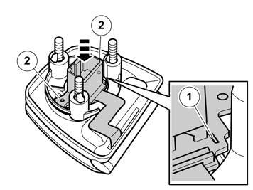
  • Place the connector in the bottom of the hole. The guide hole (1) in the connector's circuit board must align in the corresponding pin at the bottom of the holder and the holes (2) in the circuit board must be over the holder's screw turret.

8
IMG-282411
 

  • Take the small torx screws and carefully tighten the connector to the holder. Ensure that the connector's circuit board is properly against the screw turret and that there is no play.

  • Remove the butyl tape from the screws.


Preparations

9
IMG-246024
 

Preparations

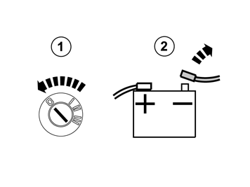
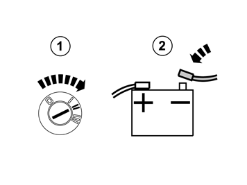
  • Turn the ignition key to position 0.

  • Disconnect the battery negative lead.


    Note!

    Wait at least three minutes before unplugging the connectors or removing other electrical equipment.


10
IMG-280165
 

    Applies to cars with automatic gearbox

  • Turn the ignition key to position II.

    Applies to all models

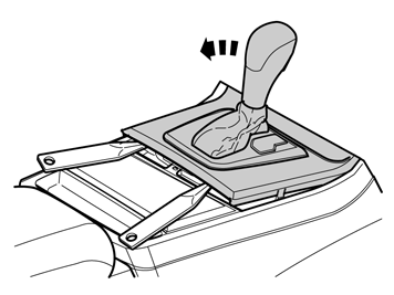
  • Move the gear selector lever to its rearmost position.

  • Use a weatherstrip and pry off the gear selector panel at the rear edge.

11
IMG-239204
 

  • Press in the catches and remove the panel.

12A
IMG-280166
12B
IMG-280133
 

Illustration A

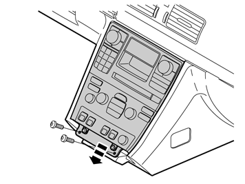
  • Remove the two screws.

  • Remove the bracket with the A/C panel and radio from the center console. Pull from the lower edge and then downwards until it releases from the mounting at the upper edge.


    Note!

    Do not damage the removed components or the surrounding panels.


Illustration B

  • Lay out a cloth to protect the tunnel console and unit. Place as illustrated. Depending on the design the cable may need to be disconnected and the unit placed to one side.

13A
IMG-296283
13B
IMG-296284
 

Illustration A

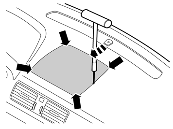
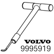
  • Remove the loudspeaker grille as follows: Insert the special tool, 9995919 into the joint between the loudspeaker grille and the dashboard approximately as illustrated, until it engages.

  • Twist the tool 90° so that the bent section engages with the underneath of the loudspeaker grille.

Illustration B

  • Pull upwards until the loudspeaker grille detaches. The loudspeaker grille is securely fastened by four clips. Move the tool closer to the clip to facilitate removal.


    Note!

    Do not damage the dashboard.


  • Lift out the loudspeaker grille

14
IMG-280107
 

  • Take the template from the kit and cut it along the outer lines.

15
IMG-280108
 

  • Tape the template to the loudspeaker grille.

16
IMG-280109
 

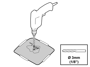
Drilling is the same on right and left-hand drive cars. Drill square to the loud speaker grille.

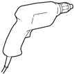
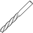
  • Predrill the holes according to the template using a Ø3 mm (1/8") drill bit.

  • Remove the template.

17A
IMG-280112
17B
IMG-280113
 

Illustrations A and B

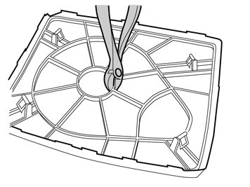
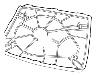
  • Turn over the loudspeaker grille and cut away some of the ribs on the underside so that the result corresponds with figure B.

18
IMG-280114
 

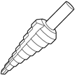
  • Drill up the three holes for the cradle's feet using a Ø14 mm (9/16") step drill.

19
IMG-280115
 

  • Take the step drill and drill out the hole for the connection in the holder using a Ø28 mm (1 7/64") drill bit.

20
IMG-280116
 

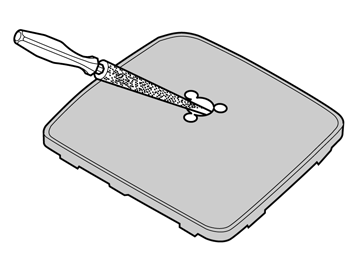
  • Deburr and bend in the edges using a round file.


Installation

21A
IMG-280117
21B
IMG-280118
 

Installation

Illustration A

  • Take three nuts, washers and the cradle from the kit and secure on the loudspeaker grille.

Illustration B

  • Tighten the cradle.

22A
IMG-280119
22B
IMG-280120
22C
IMG-280121
 

Illustration A applies to cars up to and including model year -05

Illustration B applies to cars from and including model year 06-

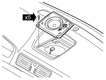
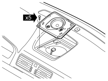
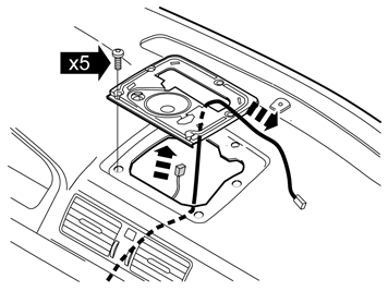
  • Remove the five screws. Lift up the loudspeaker and remove the connector.

  • Put the loudspeaker to one side. New loudspeaker and console in the kit.

Illustration C

  • On vehicles without a center loudspeaker there is a console holding the loudspeaker grille. On these vehicles the console remains in place and the cable is routed through the hole.

23
IMG-277338
 

  • Take the cable harness and foam tape out of the kit. Remove the protective tape.

24
IMG-280122
 

  • Wrap the foam tape around the fuse holder to prevent rattling.

25
IMG-280123


Note!

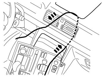
The cable harness is always routed on the right-hand side in the tunnel console and the center console up to the hole for the loudspeaker grille, on both right and left-hand drive cars.


  • Take hold of the long cable harness. Route the end with the small connector on the right-hand side in the center console, up and out through the hole for the loudspeaker grille/console loudspeaker grille.

26
IMG-280124
 

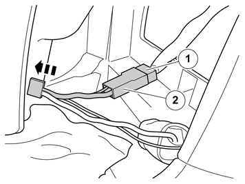
  • Take out the unit with the climate panel and connect connector (1) removed from the 12V outlet on the female connector (2) on the routed cable.

  • Connect the remaining connector to the 12V outlet.

27
IMG-280125
 

    Applies to cars up to and including model year 05

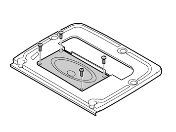
  • Remove the loudspeaker grille and loudspeaker from the kit. Secure the loudspeaker using the supplied screws. The connections on the speakers should face right.

28A
IMG-280126
28B
IMG-280127
 

Illustration A applies to cars up to and including model year -05

Illustration B applies to cars from and including model year 06-

  • Connect the connector to the loudspeaker. Route the cable to the cradle through the large hole in the speaker console.

  • Tighten the console using the five existing screws.

29
IMG-280128
 

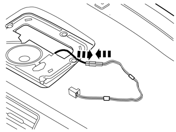
  • Take out the small cable from the kit and connect it to the recently routed cable harness.

30
IMG-280129
 

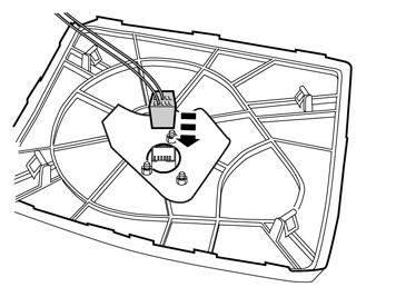
  • Take the loudspeaker and cradle. Connect the connector on the small cable to the cradle.

31
IMG-280130
 

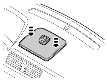
  • Insert the cable in the hole for the loudspeaker/console and push on the loudspeaker grille.

32
IMG-280131
 

  • Secure the two green connectors using a piece of butyl tape in a suitable place to prevent rattling.

  • Tuck away the surplus cable in the bottom of the center console.

  • Tie together with a cable tie.

33
IMG-280167
 

  • Refit the unit. Ensure the cables and relay are positioned so that they are not crushed or rub.

  • Tighten using the existing screws.

34
IMG-239204
 

35
IMG-279903
 

36
IMG-242267
 

  • Turn the ignition key to position II.

  • Reconnect the battery negative lead.