| | Installing lowering kit, front |
|  | | J6100374 |
|
| | Installing lowering kit, front |
|  | | J6100375 |
|
| | |
|  | | J6100376 |
|
| | |
|  | | J6100377 |
|
| | |
|  | | J6100379 |
|
| | |
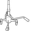
| | Pull out the drive shaft from the hub and suspend it in a suitable way. Suspend the wheel spindle on the ball joint and install the nut loosely. Use tool, part no. 9997076.
|
|  | | J7200240 |
|
| | |
|  | | IMG-275803 |
|
| | |
|  | | J6100386 |
|
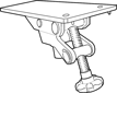
| | Remove the screw in the wheel spindle. Widen the groove in the wheel spindle. Use tool, part no. 9997088. Install it with the flat sides longitudinally in the groove and turn 45°. Carefully tap the wheel spindle downward with a copper mallet and pry down the link arm with tool, part no. 9997076 so that the wheel spindle releases from the strut.
|
|  | | J7200241 |
|
| | Remove: the three screws. the strut.
|
|  | | J7200242 |
|
|  | | J7200243 |
|
| | Illustration A Note!
Note the engaging position on the spring for easier installation of new. |
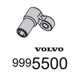
Remove: the nut on the shock absorber. Use socket, part no. 9995500, and Bihex socket as counterhold. the spring seat the rubber pad with gaiter the spring.
Illustration B Note!
Make sure that the spring seat and sock absorber bearing do not part. The bearing consists of loose balls in a frame and fall out if parted. |
|
|  | | IMG-252766 |
|
| | Applies to cars with engine alternative B4164, B4184, B4204 as well as D4164 Replace the rubber pad (3) with a new one from the kit.
|
|  | | J7200245 |
|
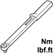
| | Install: the spring the rubber pad with gaiter the spring seat the nut (M12). Use socket, part no. 999 5500 and Bihex socket as counterhold. Torque-tighten to 50 Nm (37 lbf.ft.).
Note!
Make sure that the spring seat's marking lines up with the strut's guide when installing the spring. |
|
| | Reinstall the strut in the body with new screws. Tightening torque 30 Nm (22 lbf.ft.). Reinstall the wheel spindle on the strut. Remove tool, part no. 9997088. See step 9. Install new screw in wheel spindle. Tightening torque 90 Nm (66 lbf.ft.). Remove the nut from the ball joint and press down the link arm with tool part no. 9997076. See step 4.
Reinstall: the drive shaft with new screw. Tightening torque 35 Nm (26 lbf.ft.) + angle torquing 90°. the ball joint in the wheel spindle. Use tool part no. 9997076. the ball joint's new nut. Tightening torque 70 Nm (52 lbf.ft.). Link and nut for position sensor for the Bi-Xenon system. the brake disc. the brake caliper with two new screws. Tightening torque 120 Nm (89 lbf.ft.). the anti-roll bar link the bracket for the ABS sensor new nut (M10) for the anti-roll bar link. Tightening torque 50 Nm (37 lbf.ft). the brake hose in its bracket the front wheel. Tightening torque 90 Nm (66 lbf.ft.). Repeat the above steps for the other side.
|
| | Note!
Wheel alignment shall be performed after finished work. Information about how this is done is available in VIDA under group 6, search path: Specifications/Specifications mechanical/General /General/Specifications mechanical. |
|
|  | | IMG-275663 |
|
| | |
| | Installing lowering kit, rear |
|  | | IMG-251834 |
|
| | Installing lowering kit, rear Carried out on both sides of the car Remove the rear wheel. Remove the nut in the anti-roll bar's attachment in the link arm. Remove screw and rubber bushings.
|
|  | | IMG-251835 |
|
| | Take the pressure off the bolted flange on the link arm in the wheel spindle and remove the screw. Use lifting equipment part no. 9985972 and fixture part no. 9995972. Carefully lower the link arm until it hangs freely. Put away the the screw, new is included in the kit.
|
|  | | IMG-251836 |
|
| | Remove the old spring by first pulling down the link arm, and then pull loose the spring from attachments in the body/link arm. Remove the rubber spacer from the old spring. The rubber spacer is to be re-used. Put away the the spring, new is included in the kit.
|
|  | | D7600239 |
|
| | |
|  | | IMG-251838 |
|
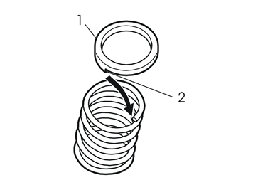
| | Install the new spring. Install the lifting equipment under the link arm again and carefully press it upward. Check that spring places itself correctly in the shoulder in the link arm and in the body. Press the link arm to correct position. Get a new screw from the kit and install it.
Note!
Do not tighten down the screw yet. The car must be in normal position when the screw is tightened. |
Repeat steps 18 - 21 for the other spring.
|
|  | | IMG-251840 |
|
| | Reinstall the anti-roll bar's ends to the link arms with screws, nuts and rubber bushings. Get new nuts from the kit (all nuts that have been removed shall be replaced). Tighten down the nuts in the anti-roll bar to 25 Nm (18.5 lbf.ft.). Reinstall the link and nut for position sensor for the Bi-Xenon system. Reinstall the wheels and tighten the wheel nuts with to 90 Nm (66.5 lbf.ft.). Lower the car so that it stands on its wheels. Tighten down and torque-tighten the new screws in the link arms/wheel spindles with 115 Nm (85 lbf.ft.).
|
|  | | IMG-242268 |
|
| | Calibrate and adjust the headlamps, Information can be found in VIDA under: Repair/Cleaning, checking and adjusting/3 Electrical system/ 35 lighting/352 lighting, front/Headlamps, setting.
|


