| | |
| | Read through all of the instructions before starting installation. Notifications and warning texts are for your safety and to minimise the risk of something breaking during installation. Ensure that all tools stated in the instructions are available before starting installation. Certain steps in the instructions are only presented in the form of images. Explanatory text is also given for more complicated steps. In the event of any problems with the instructions or the accessory, contact your local Volvo dealer.
|
| | |
|  | | IMG-363036 |
|
| | Note!
This colour chart displays (in colour print and electronic version) the importance of the different colours used in the images of the method steps. |
Used for focused component, the component with which you will do something. Used as extra colors when you need to show or differentiate additional parts. Used for attachments that are to be removed/installed. May be screws, clips, connectors, etc. Used when the component is not fully removed from the vehicle but only hung to the side. Used for standard tools and special tools. Used as background color for vehicle components.
|
| | |
|  | | IMG-354413 |
|
| | |
|  | | IMG-355063 |
|
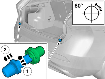
| | Note!
Note the position of each component before removal. |
|
|  | | IMG-355068 |
|
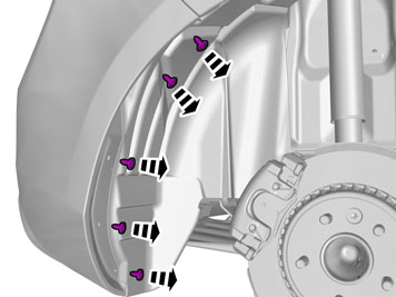
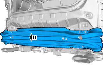
| | Remove the screws. Repeat on the other side. |
|  | | IMG-374150 |
|
| | |
|  | | IMG-355092 |
|
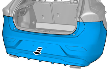
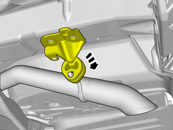
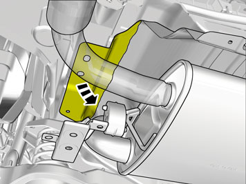
| | Repeat on the other side. |
|  | | IMG-355184 |
|
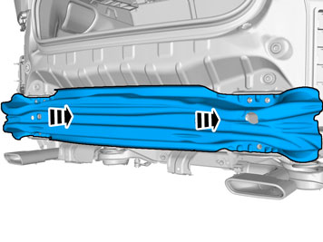
| | |
|  | | IMG-355166 |
|
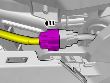
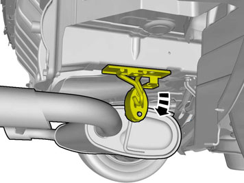
| | Request the aid of a colleague for this procedure. |
|  | | IMG-355191 |
|
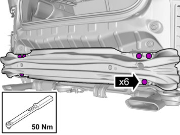
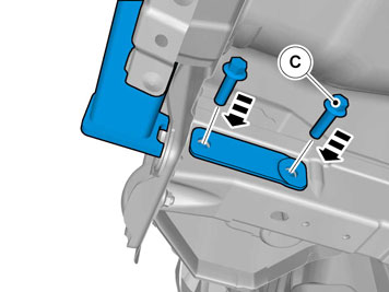
| | Note!
The screws are to be reused. |
Remove the screws.
Tightening torque: M10
, 50 Nm
|
|  | | IMG-365913 |
|
| | Caution!
The part is to be reused. |
|
| | Applies to vehicles with single end pipe |
|  | | IMG-365832 |
|
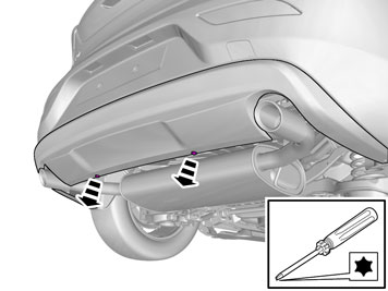
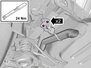
| | Remove the screws.
Tightening torque: M8
, 24 Nm
|
|  | | IMG-365833 |
|
| | |
|  | | IMG-365834 |
|
| | |
| | Applies to vehicles with double end pipe |
|  | | IMG-355199 |
|
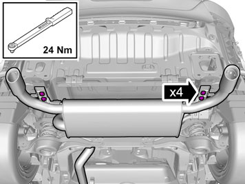
| | Remove the screws.
Tightening torque: M8
, 24 Nm
|
|  | | IMG-355341 |
|
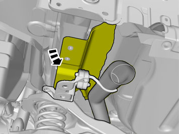
| | Repeat on the other side. |
|  | | IMG-355472 |
|
| | Repeat on the other side. |
| | |
|  | | IMG-355344 |
|
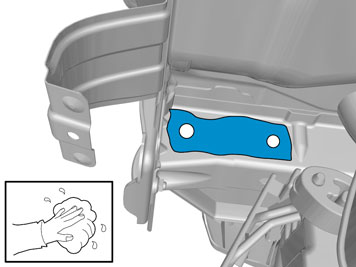
| | Scrape off all sealant from the flat surface. Clean the surface. Repeat on the other side. |
| | |
|  | | IMG-355379 |
|
| | |
|  | | IMG-355355 |
|
| | |
|  | | IMG-355356 |
|
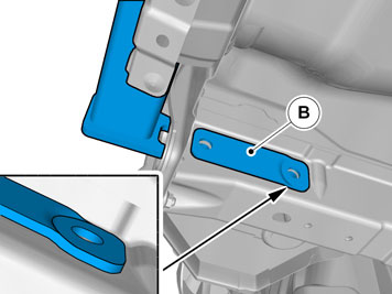
| | Note!
Only tighten the bolts finger tight at this stage. |
Install the screws. Repeat on the other side. |
|  | | IMG-368937 |
|
| | |
|  | | IMG-368941 |
|
| | Note!
Press the towbar up to its top position before tightening the screws. |
|
|  | | IMG-365812 |
|
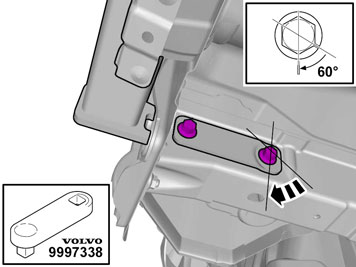
| | Repeat on the other side. |
|  | | IMG-355359 |
|
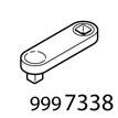
| | Repeat on the other side.
Use special tool: T9997338, Extension rod
|
| | Concerns low emission models (DrivE) |
|  | | IMG-365835 |
|
| | |
|  | | IMG-365839 |
|
| | |
| | |
|  | | IMG-363966 |
|
| | |
|  | | IMG-363617 |
|
| | |
|  | | IMG-363616 |
|
| | |
|  | | IMG-356971 |
|
| | Install tow bar connector and wiring harness according to installation instruction: Towbar, Wiring and Control Unit. |
|  | | IMG-367201 |
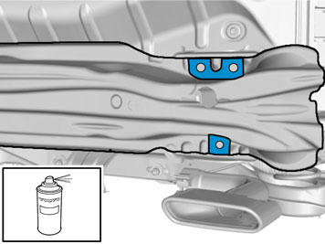
|
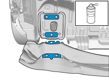
| | Use: , Rust inhibitor, low viscosity
Repeat on the other side. |
|  | | IMG-367202 |
|
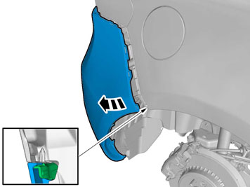
| | Reinstall the removed part. |
|  | | IMG-367329 |
|
| | Use: , Rust inhibitor, low viscosity
Repeat on the other side. |
| | | IMG-355191 |
|
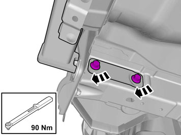
| | Install the screws.
Tightening torque: M10
, 50 Nm
|
|  | | IMG-366960 |
|
| | |
|  | | IMG-366892 |
|
| | Apply tape to the other side, opposite the marking lines. |
|  | | IMG-366881 |
|
| | Caution!
Take extra care not to damage the wiring harnesses. |
|
|  | | IMG-366893 |
|
| | |
| | |
|  | | IMG-366973 |
|
| | |
|  | | IMG-366899 |
|
| | Apply tape to the other side, opposite the marking lines. |
|  | | IMG-366896 |
|
| | Caution!
Take extra care not to damage the wiring harnesses. |
|
|  | | IMG-366898 |
|
| | |
| | | IMG-356971 |
|
| | Reinstall the removed parts in reverse order. |
|  | | IMG-355396 |
|
| | |
|  | | IMG-365793 |
|
| | |
|  | | IMG-365801 |
|
| | Attach the four corners of the label using staples. |
| | Vehicles without spare wheel |
|  | | IMG-366946 |
|
| | |
|  | | IMG-366947 |
|
| | |
|  | | IMG-355386 |
|
| | |
|  | | IMG-355388 |
|
| | |
|  | | IMG-366974 |
|
| | |
| | Vehicles with spare wheel |
|  | | IMG-366992 |
|
| | |
|  | | IMG-367016 |
|
| | |
| | | IMG-355386 |
|
| | |
|  | | IMG-367017 |
|
| | |
|  | | IMG-367018 |
|
| | |
|  | | IMG-355382 |
|
| | |
|  | | IMG-365843 |
|
| | |