| | |
| | |
|  | | A8800136 |
|
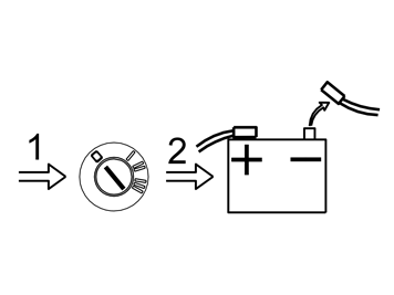
| | Turn the ignition switch to position 0. Applies to cars with manual gearboxes: remove the ignition key from the ignition switch.
Applies to cars with automatic gearboxes: leave the ignition key in the ignition switch. The key is locked in the ignition switch.
Note!
Wait at least five minutes before disassembling the connectors or removing other electrical equipment. |
Disconnect the battery negative lead.
|
|  | | J3904779 |
|
|  | | J3904780 |
|
| | Illustration A Remove the loudspeaker grille as follows: Insert tool P/N 999-5919-46 into the joint between the loudspeaker grille and the dashboard as illustrated, until it engages. Twist the tool 90° so that the bent section engages with the underneath of the loudspeaker grille.
Illustration B |
|  | | M3902613 |
|
| | |
|  | | M3902614 |
|
| | Applies to cars with centre loudspeakers Remove the screws for the loudspeaker from the bracket (1). Lift up the loudspeaker. Disconnect the connector (2). Place the loudspeaker to one side.
|
|  | | M8504883 |
|
| | |
|  | | M8504884 |
|
| | Engage the handbrake and move the gear selector lever towards the rear.
Rotate the panel to the left for better access. Remove the two screws holding the bracket with the radio and dashboard environment panel in the centre console.
|
|  | | M8504890 |
|
| | Remove the bracket with dashboard environment panel and the radio from the centre console: Pull the lower edge out and downwards until it releases from the mounting at the upper edge. Then fold backwards.
Note!
Do not damage the removed components or the surrounding panels.
|
If necessary, the panel around the gear lever selector can be removed for additional space. The panel is secured with four catches on the underside along the boot. Disconnect the connectors from the radio and dashboard environment panel. Also disconnect the connector from the phone keypad if applicable. Place the unit to one side.
|
|  | | M8503054 |
|
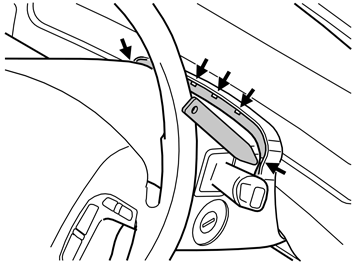
| | Lock the steering wheel in the lowest, rearmost position.
Remove the rubber seal from the upper steering column cover by carefully prying the 5 x catches loose. Use a weatherstrip tool.
|
|  | | M8502986 |
|
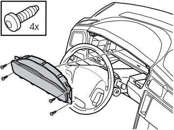
| | Pry out the 2 x clips (2) in the bottom edge of the combined instrument panel. Carefully remove the combined instrument panel surround. Pull the surround back until the 3 x clips (1) at the top edge release.
Note!
Do not damage the dashboard. |
|
|  | | M3800760 |
|
| | |
|  | | D8502410 |
|
| | |
|  | | D8502411 |
|
| | |
|  | | M8502805 |
|
| | |
|  | | A8500151 |
|
| | |
|  | | M8502823 |
|
| | |
|  | | M8502718 |
|
| | |
|  | | M8503121 |
|
| | |
|  | | M8502710 |
|
| | |
|  | | M8503130 |
|
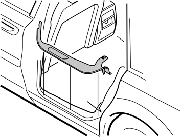
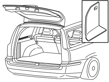
| | Remove the left side panel. Remove the cover and the screw from the front edge. Pull the top of the panel inwards until the clips release.
Fold the panel inwards. Lift the panel out.
|
|  | | M8503009 |
|
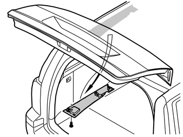
| | Detach the left-hand headlining panel from the cargo compartment by removing the screws at the rear edge. Then pull the panel downwards. Start at the rear edge until all the clips release. Remove the panel.
|
|  | | M8503153 |
|
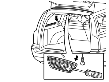
| | Remove the interior lighting in the panel at the rear edge of the roof by prying it loose. Use a weatherstrip tool. Remove the screw holding the panel. Carefully pull the panel on the left-hand side off until the clips release.
|
|  | | M3902622 |
|
| | Remove the left-hand D-post panel (1) as follows: Pull the centre of the panel inwards until the clips release. (A) Pull the top of the panel inwards until the clips release. (B) Pull the panel inwards starting at the upper/rear edge. Pull along the entire left-hand tailgate sill until the clips release. (C) Remove the panel.
|
|  | | M3703368 |
|
| | Remove the fuse holder. Open the lock (1) on the top of the fuse holder. Fold the fusebox holder forward. Lift it out of the mountings (2). Remove the black insulation panel (3), which is secured by five clips. This will not be used again. A new panel is in the kit.
|
|  | | M8503007 |
|
| | |
| | |
|  | | M3703371 |
|
|  | | M3800779 |
|
| | Cable routing Illustration A Route the wiring for the display screen and the radio (A in the kit illustration), the DIN wiring for the radio (B in the kit illustration) and the black cable to the GPS antenna (C in the kit illustration) between the air duct (1) and the stay (2). Continue to pull up the cable ends, with the blue 5-pin connector (3) for the power supply and the grey angled connector (4) for the display screen. Route to the left of the air duct above the radio cut-out to the cut out for the centre loudspeaker. Route the black cable (C) for the GPS antenna to the position behind the combined instrument panel. Clamp the wiring to the stay (2). Use the tie strap (5) from the kit.
Route the wiring above and along the air duct (1) to the member (6). Secure the wiring at the existing cable harness (7). Use the tie strap from the kit.
Illustration B Connect the GPS antenna (1) from the kit to the pre-routed cable (2). Install the GPS antenna as far into the combined instrument panel compartment as possible. Press the GPS antenna clips (3) into the existing holes. Tighten the antenna using the screw (4) from the kit. Connect the combined instrument panel connector. Reinstall the combined instrument panel. Reinstall the combined instrument panel surround. Install the rubber seal in the upper steering column cover.
|
|  | | M3703343 |
|
| | Route the wiring (1) under the carpet along the left-hand side of the car to the rear door. Clamp the wiring at the existing cable harness (2). Install the protective caps on the lugs (3) for the cable ducts.
Route the wiring further above and along the front cable duct (4). Continue along the right-hand side of the rear cable duct (5).
|
|  | | M3703344 |
|
| | Continue routing the wiring (1) along the rear cable duct (2). Disconnect the four connectors in the cable duct. Position the three cables under these. Route the wiring along the left-hand side of the wheel arch. Position as illustrated.
|
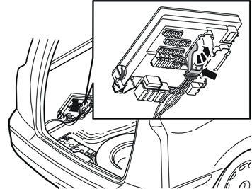
| | Connecting to the fuse holder |
|  | | M3904943 |
|
| | Connecting to the fuse holder |
|  | | D3703496 |
|
| | |
|  | | D3703497 |
|
| | Note!
Make a note of the position number of the connector. The position numbers are located on the ends of the connector and in the bottom of the fuse holder.
|
Only applies to cars with a CD changer Insert a small screwdriver in position 8 in the connector.
Locate the small spring catch on the inside. Bend the catch out of the way by inserting the screwdriver in the direction of the arrow. At the same time pull the red/white cable out. Insulate and clamp the disconnected cable. Connect the new red/white cable in the same position. Press the connector into its holder. Reinstall the connector to the fuse holder.
Applies to cars without a CD changer Connect the new red/white cable to position 8.
|
|  | | M3904942 |
|
| | |
|  | | M3703366 |
|
| | |
|  | | M3703367 |
|
| | Note!
Make a note of the position number of the connector. The position numbers are located on the ends of the connector and in the bottom of the fuse holder. |
Connect the green (GN) cable to position 20 in the connector. Connect the white (W) cable to position 21. Reinstall the connector in the holder. Reinstall the connector in the fuse holder.
|
| | |
| | Installing, antenna amplifier |
|  | | M8503123 |
|
| | Installing, antenna amplifier |
|  | | M3100208 |
|
| | Carefully pull the tailgate sill trim panel upwards by the outer edges on the right and left-hand sides until a click is heard and the clips release. Lift the panel and insert the ground lead of the pre-routed cable harness (1) into the gap between the floor support (2) and the panel and forwards to the ground terminal behind the battery. Insert the cable as far under the panel as possible. Ensure that the cable is not trapped. If the car has a CD changer remove the ground lead for the CD changer. Insulate the ground lead and clamp the disconnected cable. Connect the ground lead for the cable harness to the ground terminal. Tighten the screw. Tighten to 10 Nm (7 lbf ft).
|
|  | | M3702217 |
|
| | Does not apply to USA/AUS Position the short single cable (1) to the amplifier (D in the kit illustration) along the tailgate sill trim panel.
Note!
The cable end with the plastic connector must be on the left-hand side. |
Pull up the plastic connector to the control module. Route the other end of the cable in front of the right-hand tail lamp to the antenna amplifier. Lift the panel and insert the single cable into the gap between the floor support (2) and the panel. Insert the cable as far under the panel as possible. Ensure that the cable is not trapped. Press the panel into place. Reinstall the screws in the panel. Tighten.
|
|  | | M3903018 |
|
| | Does not apply to USA/AUS Take the antenna amplifier (1) from the kit. Connect the cable (2) to the connector (3) for the antenna in the rear bumper by the right-hand tail lamp. Position the antenna amplifier on the edge of the panel in front of the right tail lamp as illustrated. Tighten the antenna amplifier.
|
|  | | M3702788 |
|
| | Does not apply to USA/AUS Clamp the cable under the tailgate sill trim panel. Use the 4 x tie straps (1) from the kit. Connect the cable to the lower socket (2) on the antenna amplifier.
Route the cable to the left-hand rear wheel well.
|
|  | | M3903534 |
|
| | Only applies to cars with a CD changer Remove: the blue connector with the cable (1) from the CD changer. Secure the cable. The cable will not be reused. The DIN cable (2) from the CD changer. Position the DIN cable at the front edge of the CD changer. The DIN cable will be connected to the reverse of the DVD reader later.
|
|  | | M3903535 |
|
| | Only applies to cars with a CD changer |
| | Installing the DVD reader |
|  | | M3903621 |
|
| | Installing the DVD reader Applies to all models |
|  | | M3703345 |
|
| | Applies to cars without a CD changer Connect: the cable (1) for the display screen. the cable (2) with a green connector to the power supply.
the cable (3) for the GPS antenna. the cable (4) for the antenna amplifier. the DIN cable (5) for the radio.
|
|  | | M3702860 |
|
| | Only applies to cars with a CD changer Connect: the cable (1) for the display screen. the cable (2) with a green connector to the power supply.
the cable (3) for the GPS antenna. the cable (4) for the antenna amplifier. the short DIN cable (5) from the CD changer the DIN cable (6) previously disconnected from the CD changer.
|
|  | | M3903537 |
|
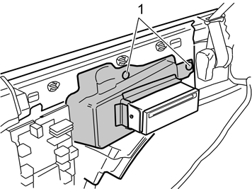
| | Applies to all models Screw the DVD reader into place with the bracket above the left-hand rear wheel well. Use the three screws (1) from the kit. Ensure that none of the wiring is caught or trapped. Tighten the screws. Tighten to 10 Nm (7.5 lbf ft). Secure the wiring behind the wheel arch. Use tie straps from the kit.
|
|  | | M8504006 |
|
| | |
| | Installing and connecting the display screen |
|  | | M3903055 |
|
| | Installing and connecting the display screen Applies to cars without centre loudspeakers Install the bracket (1) on the display (2). Use the screws (3) (from the kit).
Applies to cars with centre loudspeakers Install the bracket (1) on the display screen (2). Use the front screw (3).
|
|  | | M3903540 |
|
| | Applies to cars without centre loudspeakers Connect the wiring for the DVD reader (1) to the display (2).
Install the display screen and the bracket in the dashboard. Use the existing screws (3). Press the new loudspeaker grille into place on the dashboard.
|
|  | | M3903539 |
|
| | Applies to cars with centre loudspeakers Install the centrally mounted loudspeaker in the display screen bracket.
Tighten the loudspeaker into place. Use the four screws. Connect the connectors for the centrally mounted loudspeaker in the dashboard and the display screen bracket. Install the connector (1) for the centrally mounted loudspeaker underneath the left-hand side of the bracket as illustrated.
|
|  | | M3903541 |
|
| | Applies to cars with centre loudspeakers Connect the three cables (1) to the display screen (and the centrally mounted loudspeaker).
Press the display screen and bracket into the dashboard. Tighten using the 4 x existing screws (2). Press the new loudspeaker grille into place on the dashboard.
|
|  | | M8504046 |
|
| | Applies to all models Connect: the green female connector on the new cable harness to the green male connector disconnected from the radio. the other two large connectors to the radio. the DIN cable to the DVD reader. the remaining connectors disconnected from the radio. the connector for the dashboard environment panel. the connectors to the phone keypad, if applicable.
Reinstall: the bracket with dashboard environment panel and radio. the panel with the gear selector lever boot. the carpet. the side panel for the centre console. the sill trim panels on the left-hand side. the left-hand front seat. Tighten the front edge of the seat. Tighten the seat using the new screws from the kit. Tighten to 40 Nm (30 lbf ft). the cover above the screws at the front edge of the seat. the D-post panel and the headlining. the small insulation panel at the fusebox. the left-hand side panel. Press the surround for the DVD reader onto the side panel. See the illustration. the left-hand side cushion. the rear backrest and seat cushion. both the rear folding side panels. the front floor hatch.
|
| | Installing the keypad in a leather steering wheel/standard steering wheel |
|  | | D8501891 |
|
| | Installing the keypad in a leather steering wheel/standard steering wheel Detach both spring-loaded screws (1) on the back side of the steering wheel with a Torx T30 screwdriver. Unscrew the screws until they release from the threads and spring back. Fold out the steering wheel module (2).
Note!
Handle the cables with care. |
|
|  | | M8802904 |
|
| | Remove: the connector (1) for the horn. the SRS connectors (2). Press in the catches on the sides and carefully pull the connectors straight back.
Note!
Although the connectors are tightly secured, do not use any tools when removing. |
steering wheel module. Place the steering wheel module safely with the front side facing upwards. the screw (3), but leave the steering wheel in place. the vibration damper (4), if applicable.
|
|  | | M8802905 |
|
| | |
|  | | M3904290 |
|
| | |
|  | | M3904291 |
|
| | |
|  | | M3904292 |
|
| | Cut away some of the material on the back side of the steering wheel spoke.
Test to see if the keypad fits in the hole. If the hole is too small, cut until the keypad fits properly.
|
|  | | D3903752 |
|
| | Remove the keypad, two screws and clamp from the kit.
Make sure the cable is positioned on the correct side of the steering wheel spoke.
Insert the keypad into the hole in the steering wheel with the hook facing forwards. Make sure it connects securely against the steering column cover.
|
|  | | D3903753 |
|
| | |
|  | | M8802906 |
|
| | Insert the wiring through the hole in the steering wheel. Carefully install the new steering wheel by holding it straight and aligning the locating pins (1) on the contact reel. Remove the screw from the contact reel and reinstall the screw in the holder (see step ).
|
|  | | M8802907 |
|
| | |
|  | | D3903790 |
|
| | |
| | Plug in the connector to the connector on the steering wheel module (1) as shown in illustration . Carefully reinstall the SRS connectors (2) on the steering wheel module as shown in illustration . Position the steering wheel module and check that no wiring is trapped.
|
|  | | D8502517 |
|
| | |
|  | | A8800137 |
|
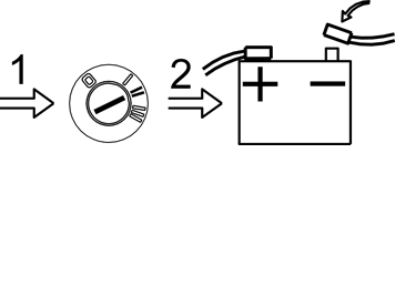
| | Turn the ignition key to position II. Reconnect the battery negative lead. Reinstall the storage box and the rear floor hatch.
Program the software according to the service information in VIDA.
|
| | Installing the keypad in a wooden steering wheel |
|  | | M6400668 |
|
| | Installing the keypad in a wooden steering wheel |
|  | | M6400670 |
|
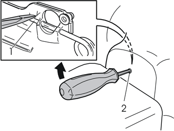
| | Insert a screwdriver in the hole along the rear edge of the steering wheel perpendicular to the rear surface of the steering wheel. Insert the screwdriver as far as possible to find the end of the locking spring (1).
Place the end of the screwdriver on the top of the locking spring. Move the screwdriver upwards towards the upper edge of the hole (2) until the spring releases and one side of the steering wheel module detaches from the mounting. Turn the steering wheel 180° and repeat the operation on the other side.
Turn the steering wheel to a neutral position.
|
|  | | M3903271 |
|
| | Fold out the steering wheel module. Unplug the two connectors (1) to the airbag transmitter cables.
Note!
Although the connectors are tightly secured, do not use any tools when removing |
Place the steering wheel module to one side.
|
|  | | M6400671 |
|
| | Remove: the screw (1) and detach the ground lead. the horn connector (2) and keypads. the three screws (3) and lift out the horn ring (4).
|
|  | | M3903760 |
|
|  | | M3903761 |
|
| | Illustration A Illustration B |
|  | | M3903762 |
|
| | Remove the keypad, two screws and clamp from the kit.
Make sure the cable is positioned on the underside of the steering wheel spoke.
Insert the keypad into the hole in the steering wheel with the text on the jkeypad facing up. Press until it connects securely against the steering column cover.
|
|  | | M3903757 |
|
| | |
|  | | M3903758 |
|
| | Position the horn ring and position it as illustrated. Plug in the installed keypad connector to the terminal on the back side of the keypad on the right-hand side of the horn ring. The cable from the installed keypad is very short and it is not easy to plug into the connector.
|
| | Reinstall the horn, according to the reversed order of operation . Ensure that the three springs are correctly positioned. Check that the ground lead is not trapped Tighten the screws alternately to 6.5 Nm (5 lbf ft).
Reinstall the ground lead. Tighten. Plug in the horn connector amnd keypads. Check the function of the horn ring by pressing around the entire edge.
|
|  | | M6400669 |
|
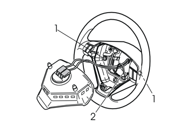
| | Check that the two springs (1) are correctly positioned. Position the steering wheel module and press the two airbag transmitter cable connectors firmly in place.
Note!
The cables must be routed through the existing holder (2). |
Insert the two lugs on the back side of the steering wheel module into the two springs and make sure the transmitter cables are not obstructed. Press the steering wheel module firmly into its mountings. Two clearly audible clicks should be heard.
|
| | |
|  | | A8800137 |
|
| | Turn the ignition key to position II. Reconnect the battery negative lead. Reinstall the storage box and the rear floor hatch.
Program the software according to the service information in VIDA.
|

